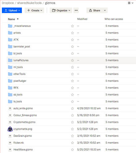
Welcome to SharedShelves!The SharedShelves Python script is an out-of-the-box pipeline solution for small production groups (or individuals) that enables multiple remote artists to automatically share their gizmos, templates, plug-ins, and toolsets with other team members using Dropbox. The SharedShelves pipeline allows artists to share plug-ins by simply placing .gizmo or .nk files into a shared Dropbox folder. The SharedShelves script will load any plug-ins found in the shared folder into a toolbar menu in Nuke with the same name as the shared folder. Other artists are then able to access the same shared tools using Nuke's tab menu or toolbar window. 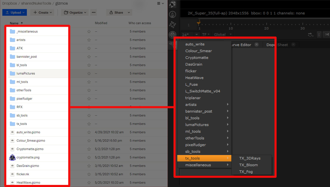 I originally wrote this script a while back when working on an indie film with some compositor friends. We all lived in different locations and we were using Nuke Indie on our personal machines to work on our shots. Our team needed a simple, on-the-fly method to instantly share templates, set-ups, and gizmos with each other. Thus, SharedShelves was born. Since the SharedShelves pipeline only needed to be installed once per artist and syncs every time Nuke launches, it quickly became an excellent way to distribute resources amongst the team. How does it work? SharedShevles uses Dropbox cloud as the backbone for its file sharing. Dropbox allows users to localize their cloud files and keep the cloud folder and local folder in sync. When a user adds a file to the cloud, Dropbox will download the file to the local machine of any user who has shared access to the cloud folder. SharedShelves will automatically pinpoint the local folder and search through it, loading up any .nk or .gizmo files into Nuke on launch. SharedShelves will conveniently place all ToolSets into Nuke’s “ToolSets” menu bar and will add all gizmos to the node bin while maintaining the same folder structure and naming conventions used in Dropbox. It’s really not much different than how you can load gizmos located in your .nuke directory with menu.py. You tell SharedShelves the name of the folder containing your plug-ins, and SharedShelves will add all the plug-in paths and commands required for each plug-in. In order for SharedShelves to function properly, each person must have permission to access the shared Dropbox folder and the SharedShelves.py Python script must be correctly installed on each user’s machine (see setup instructions) Adding and Removing Shared Tools.All you need to do in order to share and publish your gizmo or toolset is to place a copy of the gizmo or toolset into the shared Dropbox folder. This can be done inside or Nuke or by using the File Explorer (Finder). To add a plug-in using the File Browser... To add a ToolSet or gizmo to the shared toolsets using the File Browser, place the .nk or .gizmo file containing the node or ToolSet into your shared folder on Dropbox. This can either be done using Dropbox web or using the local Dropbox folder. Be sure to place the file inside a folder that's being synced with sync_toolsets() or sync_gizmos(), these folders are typically named "gizmos" and "ToolSets" respectively. Any files that are placed outside these folders will not be loaded when Nuke launches. To add a plug-in using Nuke's UI... 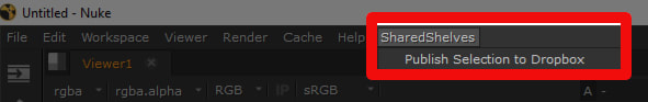
To remove a plug-in... To remove a tool from SharedShelves, navigate to the shared Dropbox folder and delete the .nk or .gizmo file Accepted File Types & Compatibility.Due to Nuke's encryption of files that come from PLE and Non-Commercial editions of Nuke, only .nk and .gizmo files are able to be shared and synced. Any files from PLE or NC version of nuke (.nknc) or other encrypted Nuke files will not be loaded on launch. This version of SharedShelves is currently compatible only with Nuke 13 or higher. SharedShevles is written using Python3 and I would like to port the script to Python2 to make it compatible with Nuke 12 and below. Until I can get around to that, SharedShelves is limited to Nuke 13 or greater. Installation Instructions.
2. Download the "SharedShelves.py" file and place it in your .nuke directory. 3. Copy the contents from "menu.py" and paste it in your menu.py file located in your .nuke directory. 4. Edit the parameters in the SharedShelves() method with your unique Dropbox information (see below)
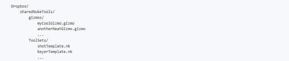
5. Edit the folder_name parameter for both s.sync_gizmos() and s.sync_toolsets() to EXACTLY match the name Dropbox folder where your gizmos and toolsets are stored. For example, if your gizmos are stored in Dropbox/sharedNukeTools/myGizmos, your sync_gizmos would be s.sync_gizmos("myGizmos"). By default, sync_gizmos() will look for a folder named "gizmos" and sync_toolsets() will look for a folder named "ToolSets". 6. Launch Nuke! Using the above examples, my SharedShelves class would look like this:
Downloads.Downloads and further instructions can be found through the GitHub link below.
SharedShelves GitHub Download Link
0 Comments
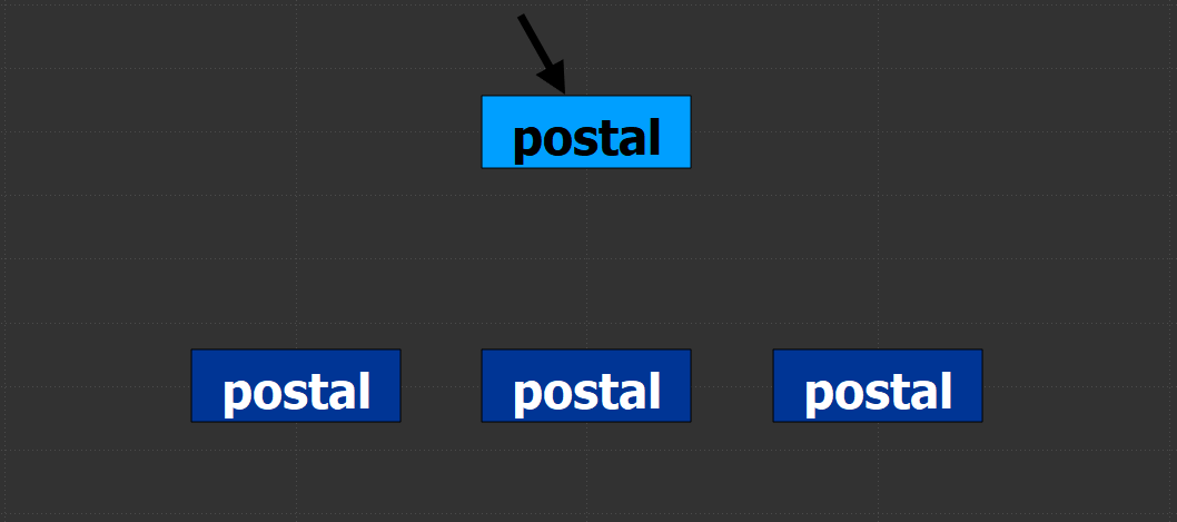 background.I started using Adrian Pueyo and Alexey Kuchinski’s Stamps tool a little while back and absolutely loved the positive impact it had on my comps. It became much easier to manage read nodes and pipe different aspects of the comp such as masks and CG passes around my script. Eventually, an issue was discovered by the systems team where creating too many stamps would cause issues loading up the script in the future. While this is most likely an issue with the complex pipeline itself and not the actual Stamps tool, I decided to create a boiled down basics version of the Stamps plugin for personal use which won’t cause pipeline issues down the road. Watch the demo video for Postal below: instructions. Postal is great for keeping your Nuke scripts neat and organized. It works similarly to Stamps in which there are anchored parent nodes and floating child nodes. The parents are to be locked to a single node (like a read node or a matte) and the children, linked to the parent, disperse the input around the script as needed. This allows compositors to create a setup in one location and distribute the output around the script without copy/pasting reads or creating a spaghetti bowl of dots and lines. It’s quite easy to use:
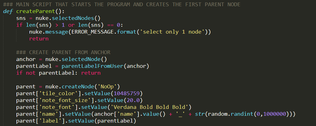 code snippets. Overall, the code for this tool is fairly basic, mostly creating nodes, some custom knobs, setting inputs, and changing values. There were two primary hiccups that I came across when developing this tool, both of which required some digging into how Nuke runs under the hood. The first of which was learning how to have two nodes share the same name while the second tackled how to get PyScript buttons to run the code I wanted them to. Both of these areas were new for me and while my code works, there may be better ways to implement these features. autolabel children. The first challenge when developing this tool was to find a way to have two nodes share the same name. When a new parent is created, the user specifies a name for the parent and a child with the same name is created. Typically, nuke doesn’t allow two nodes to share the same name. If there’s a node named “Blur1” and you try to rename a different node as “Blur1”, Nuke will throw an error “The node Blur1 already exists”. So how can it be possible to have the parent and child share the same name? By overriding the default Autolabel knob in the child node to match the parent! Every node in Nuke has a hidden knob called Autolabel which controls how Nuke should name each node as they’re created. Using Python, we can override this default action and replace it with our own. changing the autolabel knob in the child node
Here’s a piece of code that runs when creating a new child node. In this code, we navigate to the child node that’s just been created and select it. Then, we set the value of the child’s Autolabel knob to label from the parent. Any code that we want to be executed inside the Autolabel knob must be passed in as a string, otherwise Nuke will throw an error. This will allow both the parent and the child node(s) to share the same name. Stefan Ihringer’s Comp-Fu blog has a great write-up on how Autolabel functions. I'd highly recommend skimming through this, understanding the Autolabel knob unlocks some powerful customization options for the programmer. pyscript buttons. Another bottleneck I stumbled upon was getting each PyScript button to execute the correct piece of code. PyScript knobs expect an input of some Python code stored in a string. Once some code is stored in the PyScript knob, it will be executed whenever the user presses the button. However, it seems as though the PyScript code executes “in it’s own world” meaning that it’s not possible to pass variables from the main script through to the to PyScript. This is the case because the main script has already finished executing by the time any user will be pressing any PyScript buttons. This means all the variables that were created for the main script have been discarded by the time a user wants to press a PyScript button. To work around this, I split out the different functions that need to be run into separate .py files and made sure to include an import statement for that .py file inside the PyScript button’s code. adding code to a PyScript knob
Above is an example of how I created a PyScript button. First, I created a multi-line string called CREATE_CHILD_PYSCRIPT which stores the script that will be executed when the user presses the “create child” button. Note that the script first imports the create_child python file before executing the function. This allowed me to edit the script with Python syntax, otherwise the script would have to be written as a string inside the main function. This makes it so having the script installed is necessary in order for the tool to function but greatly improves human readability of the code. conclusion. This was a fun and thought-provoking project that I’ll be keen on keeping up to date as time passes. I definitely see myself using a tool like this as I can’t go back to comp life “pre-Stamps” . I'll always want a powerful organizational tool like this in my lineup. Feel free to reach out with any questions or issues you may come across when using this tool. Happy Comping! downloads.
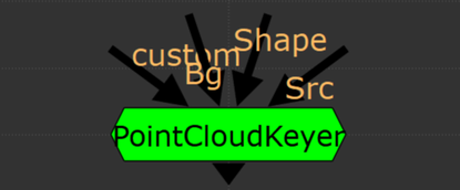
 keying in the 2nd dimension. A while ago, I came across a post on Eran Leroy’s blog that blew my mind. He demod a 2d keyer using STMaps to generate a point cloud that could be masked with a roto shape to output an alpha. I think this method has potential to get some use in keying a variety of subject matter, so I decided to package up the demo from the blog into a functional keyer. Nuke primarily has three types of keyers, 1-dimensional, 3-dimensional, and algorithmic . 1D keyers create an alpha channel from a single channel (LumaKeyer), algorithmic keyers work by comparing two channels against each other (Keylight), and 3D keyers plot one channel per XYZ axis and define a 3D shape for the keyed areas (Primatte). Nuke pretty much has it all for keying, except for the 2-dimensional keyer. This tool takes keying to a whole new dimension. A quick note: the core of this tool revolves around using STMaps, Ben McEwan has a good write up on how they work if you need a refresher. instructions.
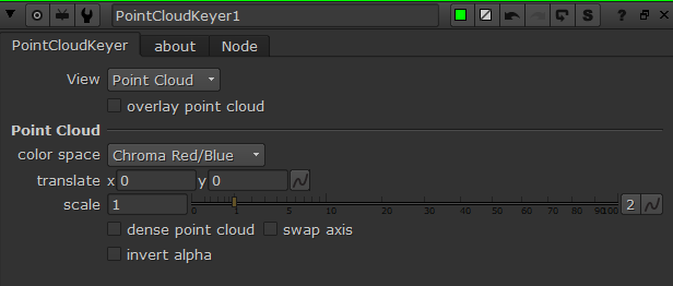
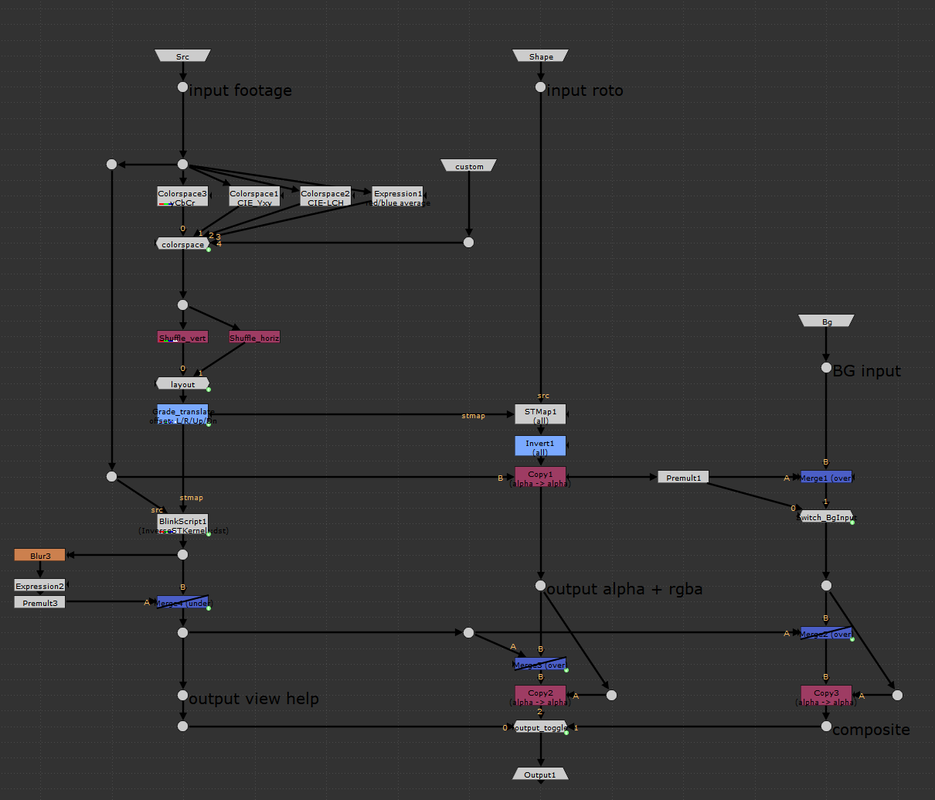
some definitions. Before diving into the guts of the group, it’s important to have a surface level understanding of a few key terms. Color space is a mathematical interpretation used to describe the color of light, displayed as three numerical values. Luminance or value can be described as the “brightness” of light i.e. dark blue vs light blue, we’re talking about the different shades of light in the blue, not the color.  Chrominance refers to how intense the hue and/or saturation of a given color is. Colors with low chrominance are “weak” while colors with high chrominance are vivid. Chrominance is often, but not always, described using two color channels.  STMap is a Nuke node that moves pixels around in an image based on a two-channel UV map. The two channels correspond to the (x, y) “absolute position” of each pixel in the image. The values in the UV map are between 0 and 1 where (0,0) is the bottom left of the image, and (1,1) is the top right. The STMap node moves the pixels from the ‘src’ input based on the values of the two-channels in the ‘stmap’ input. For those that understand written code better than words, here are the workings of the STMap node in a BlinkScript kernel that might help explain what’s happening under the hood of the STMap node a bit more. 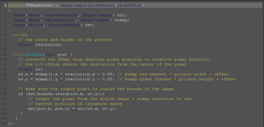 separate luma from chroma. The three channels that make up a layer inside Nuke can represent various components of color as well as other types of data. Many familiar color spaces store the amount of red, green, and blue light in their respective channels (linear, rec709, log, etc.). The color spaces most useful for this tool are those that store the luminance information separately from chrominance information. An example of such a color space is one familiar to many artists, HSV, which uses an individual channel for hue, saturation, and value (luma, sometimes called brightness). The default color space used in this tool is the YCbCr color space, where Y denotes the amount of luminance (brightness), and Cb and Cr the blue-difference and red-difference, respectively. Color science is a large box that we don’t need to dig deep into for this tool; the important information to hold on to is that certain color spaces let us separate two-channel chrominance information from single-channel luminance information. 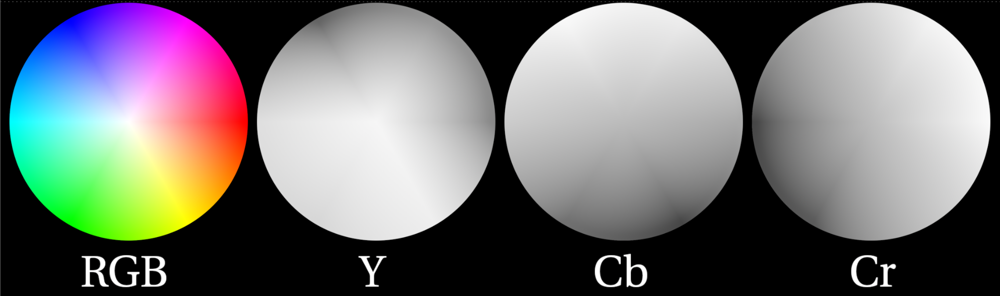 The image above shows the components of the YCbCr color space that work to create the RGB image on the left. The Y channel is solely the brightness of the overall image. The Cb circle shows the amount of blue chrominance in the image. Note the area near the top left contains values closer to white (lots of blue chrominance) while the bottom right displays values closer to black (no blue chrominance). The Cr cirlce shows the amount of red chrominance in the image. Again, note the areas of white vs black. Finally, note how the greens are represented in this color diagram. Green has very little chroma red or blue but lots of luminance. This will help us plot the chroma information and draw an alpha channel later. the basic setup.
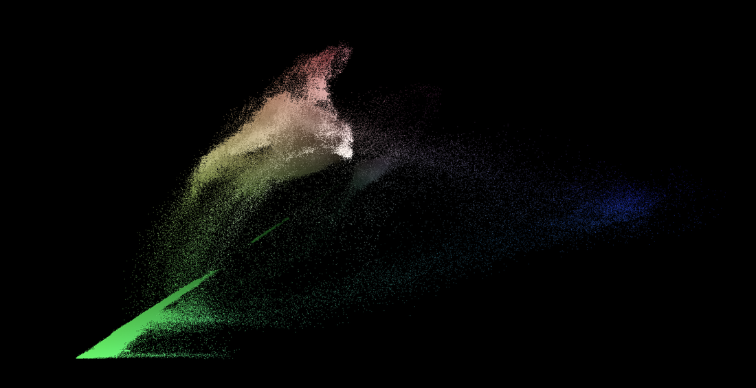
generating the point cloud visualizer. We can plot one channel of chrominance on the x-axis of the viewer and the other channel of the chrominance on the y-axis using an inverse STMap BlinkScript kernel that Mads Hagbarth created and Erwan Lery adapted for use in this tool. This is the reverse operation as the STMap kernel posted above.This kernel generates a 2D point cloud that maps the source footage based on the Cb and Cr chroma channels. The x-axis of the point cloud represents the amount of blue-difference (Cb) in the image, the more “blue” a color has, the further on the positive x axis the pixel will be plotted. Similarly, the y-axis represents the amount of red-difference in the image, the more “red” a pixel has, the higher on the positive y axis it will be plotted. This leaves pixels with high values of “green” to remain closer to the origin. This point cloud separates out the screen color of the green (or blue) screen from the rest of the foreground, which makes masking the screen colors with the roto shape much easier.
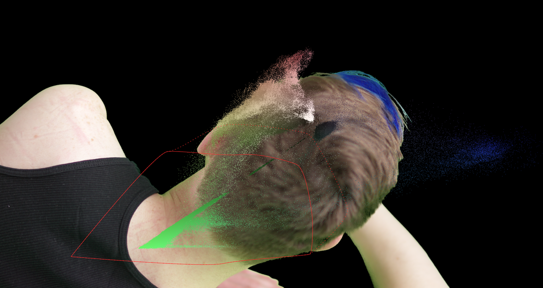
However, there are still a few quality of life adjustments that can be made to the point cloud. Firstly, I’ve added two different shuffle nodes for swapping the axis of the point cloud. This could be helpful in separating out the chroma values for easier masking. Secondly, there’s an added grade node that’s used to transform the point cloud. The blackpoint and whitepoint can be used to scale the point cloud up and down, as needed. The offset value of the grade will translate the point cloud in the x and y. Tertiarily, I’ve added a simple blur and premult to add more density to the individual point cloud pixels. Finally, my favorite addition is the ability to overlay the point cloud over the source footage. This makes fine tuning the alpha channel a much smoother experience as the user can see the point cloud and the output alpha at the same time. downloads. I hope this tool finds a home in the Nuke artist’s ever expanding repository of keying techniques. This is definitely one of the more unique ways to manipulate pixel information that I’ve come across and it’s been an exciting adventure dissecting the inner workings of STMaps.
Happy comping! 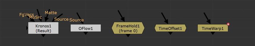 retiming is an essential headache.
retiming using an expression. The expression used to retime an animated knob depends on the node that’s doing the retiming. Different retime nodes have timing knobs with different names which must be accounted for in the expression. It’s quite simple to set up these expressions. First click on the knob in the node that you need retimed and press “=” to begin editing that knob’s expression. Next, type the expression which will vary depending on the type of retime node that you’re using. This may be confusing for those who aren’t comfortable with Nuke expressions so I’ve listed what the retiming expression is for a handful of Nuke nodes. FrameHold
This one is pretty straightforward, the knob we’re looking for is the “first_frame” knob in the FrameHold node. This knob tells Nuke which frame we’re going to be freezing on and as such adding this to any animated knob, will freeze it’s animation on the designated frame. This is useful for setting up camera projections without having to clone or copy/paste multiple FrameHolds. TimeOffset
TimeOffset will be offsetting the values of the animation by a specified value. Here, we need to grab the current frame using “frame” and add the offset value from the TimeOffset node. The output would be the same as if you placed a TimeOffset node downstream of the node with the animation. TimeWarp, Kronos, and OFlow
The TimeWarp, Kronos, and OFlow nodes all use a similar syntactic method to each other, but require different expressions based on the timing method selected in the node. For these expressions, Nuke will be looking at the frame number specified by the TimeWarp, Kronos, or OFlow, and use the input value at the specified frame. If the frame is non-integer, Nuke will interpolate the timing curve and create a new value. In short, Nuke will look for the retime node’s “timing lookup” knob and grab the value from the curve at the frame specified by the lookup. It gets slightly more involved with OFlow and Kronos because these nodes have multiple methods of retiming their inputs. The expression used to retime an animation from a Kronos or OFlow node will depend on the value of the “Timing” knob in the OFlow or Kronos. the meat of the code. This script isn’t the most complicated piece of python (although it was much more complicated than I had expected, more on that later) in short, we look at the user’s current selection of nodes, pick out the node doing the retiming, then loop through the rest of the nodes looking for animated knobs and setting an expression on that knob based on the selected retime node The primary method of the script
We start in the retimeKeyframes() function which looks at the users current selection and does some validation checks to see that the user has something selected and that the first node they selected is a node that can do some retiming (framehold, kronos, oflow, timeoffset, timewarp). We then call the getAnimatedNodes() function which loops through the selection and picks out any nodes that have some animated knob on them. This function looks at every knob in each node in the users selection and checks for two conditionals. First, the knob that we're looking at has to be the type of knob to be retimed, we’re mainly looking for knobs that store numerical values. Secondly, we need to see if that knob is animated using the knob.isAnimated() function which will return True if that knob has some keyframes on it. If both of those conditions are true, we’ll add that node to a list and return that list. Getting the animated nodes
Next, we’ll loop through each node from the list we gathered and set the expression on the animated knobs. In this loop, we’ll look at each knob in the node and see if that knob has some animation on it. If so, we’ll have to then loop through each curve in that knob (what I call sub-knobs). We can do this with the built in method node[knob].animations(). This method returns a list of all the sub-knobs that have keyframe animation attached to them. For example, a transform node has a knob called ‘translate’. This translate knob is what Nuke calls an ‘XY_knob’ which contains two fields, one for the x value and one for the y value. If you tried to use knob.setExpression() on the XY_knob itself, Nuke will have no problem with this and will set the expression on BOTH the x and the y sub-knobs. This usually won’t cause any issues however, if the user has animation they retimed on one of the XY knobs while the other knob has no animation and is a value other than 0, the added retime expression will cause knob with a non-zero value and no animation to be the output of the expression multiplied by that value. This is no good! The user would expect their constant, non-animated value to remain consistently not animated. Here’s an example, let’s say we have a transform node with the x field on the translate value set to 50 and the y field has some keyframed animation. If we apply the expression (Kronos1.timingFrame2) to both knobs, the x field will output the value of 50*Kronos1.timingFrame2, which would be an unexpected output. That x value would then become animated based on the Kronos even though it had no animation to start with. To address this issue, we need to call setExpression() on the sub-knob and not the parent knob. That’s why this function loops through the sub-knobs as well. Setting the retime expression
Finally, we use a function called getRetimeExpression() which returns the correct expression for the knob based on the node that’s doing the retiming. As stated in the prior section, different retime nodes use different expressions to apply their retiming. This function simply checks the knob class and some values of knobs within the retime node, and returns an expression to do the retiming. Creating the retime expression
where the code falls short. The biggest blind spot of this code is that it will only work if the knob that’s getting retimed is void of any expression other than “curve”. If the knob to be retimed has some other user created expression, this script will override that expression. I took some time to try and fix this, but I never found a solid solution and came to the conclusion that it would be a rare occurrence that this would happen anyways. A “work around” would just be to retime the node that’s driving the expression in the first place. If someone runs into a situation where this design choice becomes a hindrance, I’d love to hear about it and work out a better solution. A potential second blind spot is that if the user is using a Kronos or OFlow to do the retiming, they might want to change the timing method after running this script. If the user changes the timing method, for example, from “frame” to “output speed” after this script has applied the expressions, the expressions won’t update to accommodate that change. A potential solution to this problem might be to update the getRetimeExpression() function to output a TCL conditional that checks the parent retime node for which timing method is being used, and update the timing expression to match. problems I encountered. While working on this project I ran into quite a few roadblocks that forced me to rethink my approach. Overall, the majority of the issues I encountered were completely self inflicted, many of the technical and syntactical aspects of the project were simple enough to figure out with an internet search or through doing my own testing. I started to step on my toes when I went diving into dictionaries to store all the node/knob/sub-knob relationships. I had a dictionary nested in a dictionary which was nested in yet another dictionary. The for-loops required to parse this complex list was a headache to wrap my head around. This dictionary issue stemmed from me trying to execute too many tasks in one step. I should have tried the simplest method first instead of over-engineering a solution in my head. I got first draft of the script working for a single node, I then wanted to extrapolate the script to work on a group of selected nodes. Instead of taking my solution that worked for one node and applying to a list of all the nodes, I went about gathering a huge nested list of all nodes, knobs, and sub-knobs and then tried to parse through this complicated list. In my finished script, I scrapped the dictionaries entirely and applied my single node solution to a list of only the required nodes. This made my code so much easier to read and understand and debug later down the line. know it for next time. On the next Python project that I take on, I’ll need to keep in mind that a node’s knobs are not simply a one dimensional object; knobs are made of sub-knobs and I need to structure my code to work for the sub-knobs first. Furthermore, I’m glad I learned how to leverage node.animation() and node.animations() to quickly get the keyframe information I required. Understanding how these functions worked marked a dramatic turning point in how I was approaching this problem. I also need to keep an eye out for “smelly code” which are sections of code that could be written more elegantly or provide more flexibility. I came across a series of videos on YouTube by Derek Banas on refactoring code that was eye opening to me. At the time of watching this series, my code was a jumbled stinking mess that was so complex, I could barely understand it. After watching a few of these videos, I realised how much I could improve the functionality and readability of my script. If you’re getting off the ground with scripting I’d highly recommend taking a look at this video series. in conclusion. I see this script being put to use on a shot-by-shot basis, rather than being a staple program loaded on board a complex pipeline. It might only get used a handful of times on a given project yet, it has the ability to save that one poor artist (me) a bit of time when dealing with shots containing temporal manipulations. While this script might not be a groundbreaking change to visual effects pipelines, it is very easy to implement and can be added to any compositor's toolbox in a flash. Thanks so much for taking time to read through this summary. I urge any experienced programmers to delve into my script and point out any potential weak points and let me know how I could improve upon this to make the script bulletproof. I’m always looking to improve upon my programming skills and your input would be most appreciated. Happy comping! downloads. This script requires minimal setup, at its simplest you can copy/paste the script into Nuke's script editor and make sure you call the function by typing, on a new line, retimeKeyframes(). Then, select the nodes you want retimed, then highlight the script and press ctrl+enter to execute the script.
If you choose to pre-load the script from .nuke, I'd recommend setting up a Python folder, loading the folder from init.py and adding the script to a toolbar in the .nuke. The GitHub link provided is set up as such. You can find download links to this script on my GitHub: 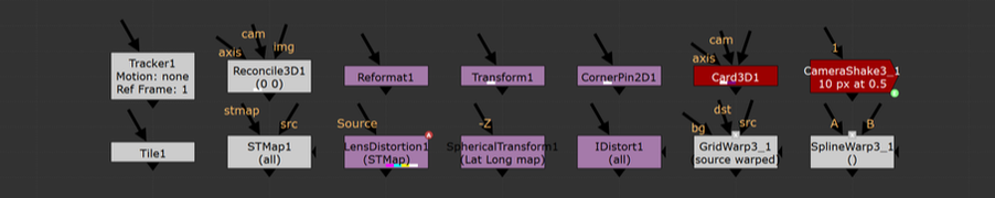 the basics.An understanding of how Nuke handles 2D image transformations is essential for all Nuke artists, even if that understanding just scratches the surface level. Filtering methods and concatenation play an enormous role in maintaining the quality of the plate. The importance of reducing the degradation of the plate while working can not be stressed enough. There are a handful of great write ups on filtering for Nuke out there but since this topic is so important for all artists, I want to make that information more accessible for every compositor out there. filtering muddles your comps.A “filter hit” happens when Nuke resamples an image to remap each pixel coordinate to an integer value. Taking a filter hit will slightly degrade the image and will often be unavoidable at one point or another. Taking a few filter hits on different areas of the frame will most likely be okay, but the problems quickly emerge when multiple filter hits are needlessly created. In order to transform an image, Nuke will take the input coordinate of a pixel, apply the spatial transformation specified by the user, and then output the destination value for every pixel in the image. Filtering is necessary to help prevent jagged edges from appearing by applying an anti-aliasing filter across the image after it transforms. So what happens when the user places a transform node down and applies a translation of 0.5px in the x direction? A computer monitor is comprised of a coordinate grid of pixels where every pixel has an x and y value and every pixel is assigned a color. The values of each coordinate must be an integer because a pixel can only display a single color at a time. Transforming an image by half a pixel would prevent the image from being displayed on the monitor unless a filtering method is used to calculate integer values for all pixels before displaying. In essence, this is what’s happening when the user is applying transformations in Nuke. The user will apply a transformation which will create a whole bunch of non-integer pixels and Nuke will round those values into integers based on the filtering method that’s selected. A simple filtering method uses the original pixel values, while more complex algorithms apply sharpening and smoothing to make a more natural looking image. Choosing which filter to use can have a large impact on the quality of the output. The image below shows how Nuke handles an image transformation of 0.5px. Both images have a single white pixel in the center of the workspace. Image A uses a transform node with no translation, while image B shows the 0.5px translation. As you can see, the filter interpolated the 0.5px translation as two pixels each half the value as the original. Imagine doing this pixel "halving" across an entire image 2 or 3 or 4 times over, the overall image quality will surely degrade. 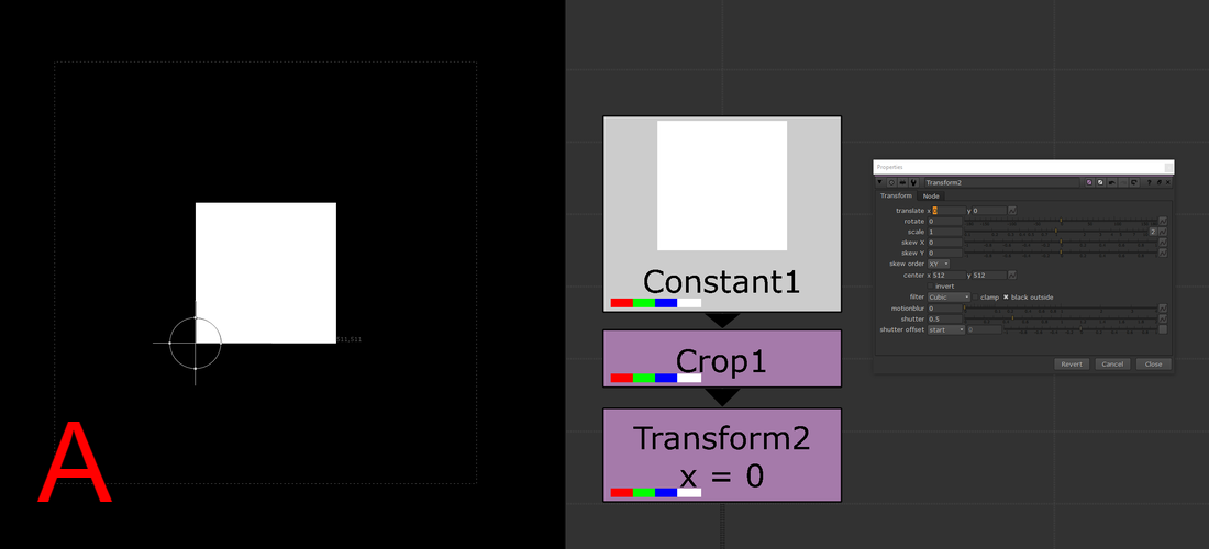 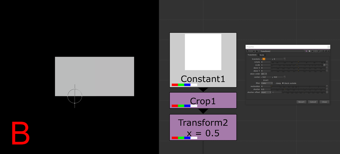 filter or motion blur or both.The quick rule of thumb to follow is that nodes with filter, motion blur, or both of those knobs will have some sort of filtering when used. Some examples include, but are not limited to, transform, card3D, spline warp, lens distortion, tracker, scanline render, and corner pin. Keep in mind that if the motion blur option is being used in any of these nodes, there will be two filter hits because motion blur is a filtering method on its own (Nuke processes spacial filters first then temporal). Furthermore, if you stack multiple transforms one after another, only the filtering method of the bottom-most transform in the stack will be applied, all others will be ignored. (see the “concatenation” section below for more details) choosing the right filtering method.The large amount of filtering methods available make choosing the right one for you a daunting task. I’ve divided the methods into different categories to help you choose the right method for your needs. At the top of the list are the methods that add the most sharpening to the image. As you move down the list, the methods become more smoothing intensive with the most smoothing at the bottom. I'd recommend experimenting with the different options to learn the unique properties each one has.
Heavy Smoothing Other
Additional information and further examples on the different filtering methods can be found on Ben McEwan's filtering blog or on Foundry's webpage on filtering. concatenation.All of the above information is great surface level knowledge on dealing with filtering in Nuke. Understanding how concatenation works in Nuke is the deep level knowledge that will sharpen your artist’s eye to better pick out minute details in your comps. Concatenation is one of the most important pieces of 2D compositing knowledge that any artist can start applying immediately. Above, I mentioned how you want to minimize the amount of filter hits that are needed to produce the final output, an understanding of concatenation is an understanding of how to minimize the damage on your plates from filtering degradation. Concatenation is Nuke’s ability to combine adjacent transformation operations into a single operation, which will be filtered a single time. Ben McEwan’s blog on filtering (link above) provides a great example. Rather than taking multiple operations with stops in between: 5+10 = 15, 15+2 = 17, 17+8 = 25; Nuke will do all those operations at once: 5+10+2+8=25 but only if the nodes performing the operations are of similar type (have a filter knob). Each of these operations is a link in the “concatenation chain” and at the end of the chain, Nuke will filter the values and display the image. Concatenating nodes of similar type will continue to add links in the chain until a non-concatenating node is added, at which point the chain will have break and a filter hit applied. When it comes to filter hits, you want to be minimizing the amount of broken links in your comp. 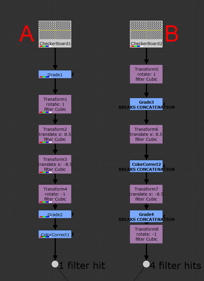 With the Transform node, you’ll want to be adjacently stacking the transform nodes in order to keep the chain links connected. Nuke will look at this stack and treat it as if it was a single transform operation and apply one filter method at the end of the stack. Since Nuke is treating the stack as a single operation, the rule is that only the filter at the end of the stack will be used, all filters above will be ignored. The image above shows two setups of identical nodes arranged in differing orders. Stack “A” minimizes filter hits from concatenation by arranging the transform nodes one after another in a linked chain; there aren’t any nodes between the transforms. This outputs an image with only one filter hit. Contrast that to stack “B” which has nodes breaking the transform chain. This output takes four filter hits while computing and the resulting image looks noticeably worse off. Take a look at the two outputs below, notice the fuzziness of output “B”. Four filter hits can make a huge difference!  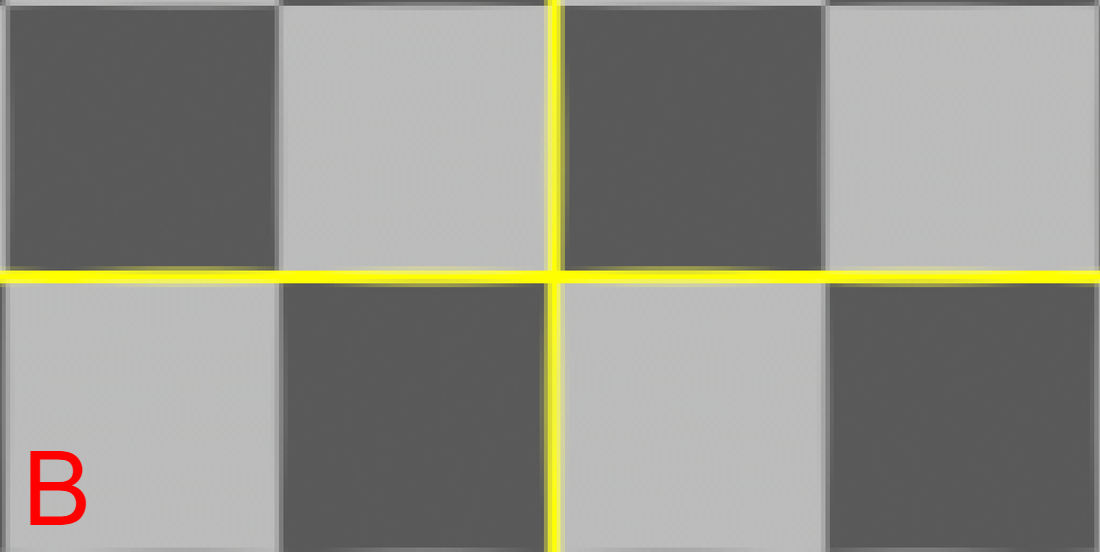 upstream and downstream.Not all filtering nodes play nicely with others. A handful of transformation nodes will end the concatenation as soon as they’re placed, without exception. Nodes that are upstream compatible will concatenate with nodes placed above, but will always cause a break in the chain below. The “motion blur” knob is an example of upstream compatibility. The motion blur knob in a transform is its own filter and when enabled, will add a filter hit alongside the spatial filter. If a transform node has the motion blur option enabled, it will always break the chain when it’s calculated. Other nodes are upstream and downstream compatible meaning they will play nicely with other transforms above and below without breaking the chain. Below is a comprehensive list of all concatenating nodes and their respective behaviors. Any node that is not on this list will cause a break in the concatenation chain. The quick rule of thumb to determine compatibility is that if the node has a filter and a motion blur knob, it will be upstream and downstream compatible. If the node has only a filter knob, it will only be upstream compatible. If a node has neither of these knobs, it will not concatenate (unless it’s a NoOp, dot, or switch). The only exception to this rule is for the reformat, which will concatenate upstream and downstream. 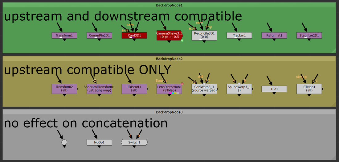 a note on 3D.At the very bottom of the concatenation knowledge ocean is knowing how 3D nodes will concatenate. Nuke is quite smart and will continue linking the chain of concatenation through the 3D system as long as no other breaks stop it. 2D transforms can be passed through the 3D system and to the ScanlineRender while still maintaining their concatenation. “Regular” Nuke geo (card, cube, cylinder, etc.) will not break concatenation. However, any imported geo will cause a filter hit. Furthermore, Project3D will not cause any damage which is quite powerful. I constantly find myself using Project3D in my cleanup work and knowing how to keep my images looking sharp even while getting passed through 3D is a huge improvement. a note on anamorphic footage. When working with non-square pixel aspect ratios in the past, I had become accustomed to using the Reformat node to dequeeze anamorphic plates, causing a filter hit right at the start of the comp. This filter hit can be removed entirely by setting the project settings to the desqeezed aspect ratio while also having the “ignore pixel aspect” checkbox disabled in the viewer node (the hotkey for this is ctrl+shift+p with the mouse hovering over the viewer). Nuke is typically good at maintaining image integrity when desqeezing using a reformat so the overall degradation of the plate is minimal here. Filter hits can add up fast and removing a filter hit entirely is an always welcome addition. minimizing the damage.More often than not, when using a high-sharpening filter, some sort of artifacting will become apparent. Look into areas of high contrast or super hot white values and you might notice a ringing that is typical of many sharpening algorithms. One way to combat this is to move to a log colorspace before applying the sharpening. I use the ColorSpace node set to “AlexaV3LogC” before I apply a heavy sharpening method to reduce the visual artifacting that may occur. Keep in mind the rules of concatenation here and be careful not to break the chain. High sharpening algorithms have the tendency to create negative values in their outputs, which can lead to a whole sort of issues down the line. It might be worth placing a clamp node to clamp the blacks to 0 in order to remove any negative pixels that have popped up. Remember to disable clamping for the whites. in closing.Phew! That’s all I’ve got for this subject. Filtering and concatenation is a dense topic that has major implications on the quality of plates in your comps. I constantly find myself learning new tidbits here and there on the intricacies of concatenation and the nodes that play into it. I hope you learned something new from this write up. Happy comping!
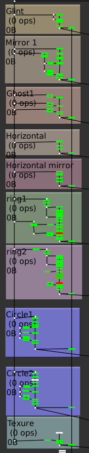
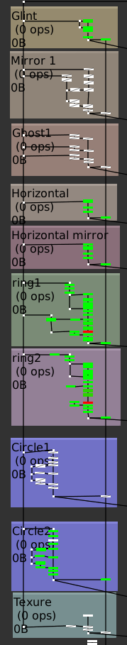
the how toIn this tutorial I cover how to setup and use the UV projection mode in the ScanlineRender node to make cleanup a breeze in Nuke. In my experience, I've found myself using this method to paint out dolly tracks or other objects on a flat surface. It's also came in handy when doing cleanup on pattern surfaces where painting from the camera's perspective might be challenging. The only thing you need to get this method working is a tracked camera for your shot. The better the camera track, the easier this type of cleanup will be. To get started, you'll need to place a card in 3D space over the area which you want to do your cleanup on. Think of this card as your cleanup canvas, anything that falls inside this card's area you'll be able to work on, anything that falls outside the card's area will not be able to be used. This method can be repeated using multiple cards if necessary. I used a PointCloudGenerator node to help me confirm that my card was where I wanted it in 3D space. Next, take a Project3D node and hook the inputs in to the tracked camera and the BG plate. Take your card and plug that into the Project3D. Next, drop in a ScanlineRender and hook that into the card. Set the "projection mode" knob on the ScanlineRender to "UV". This will have the ScanlineRender output the UVs of whatever geometry is plugged in, which is where we're going to be doing the cleanup. This ScanlineRender does not require a camera to be plugged in because UV maps can exist independently of the camera. Think of it like modeling geometry when in a 3D package. You can model the geo with UVs without needing a camera in your scene. With the viewer hooked up to the ScanlineRender set to UV, start working through the cleanup. After you've finished the cleanup, it's time to reverse the UV stabilize that we had set up above. Copy the card that was created earlier and hook it up at the bottom of your cleanup. Next, place a ScanlineRender node and connect the camera input to the tracked cam, and the obj/scn input to the copied card. This ScanlineRender needs to have its "projection mode" knob set to the default "render cam". Finally, merge your completed cleanup over the BG plate. All done! The image below shows the basic setup for using this stabilization technique. Thanks for reading and happy comping! 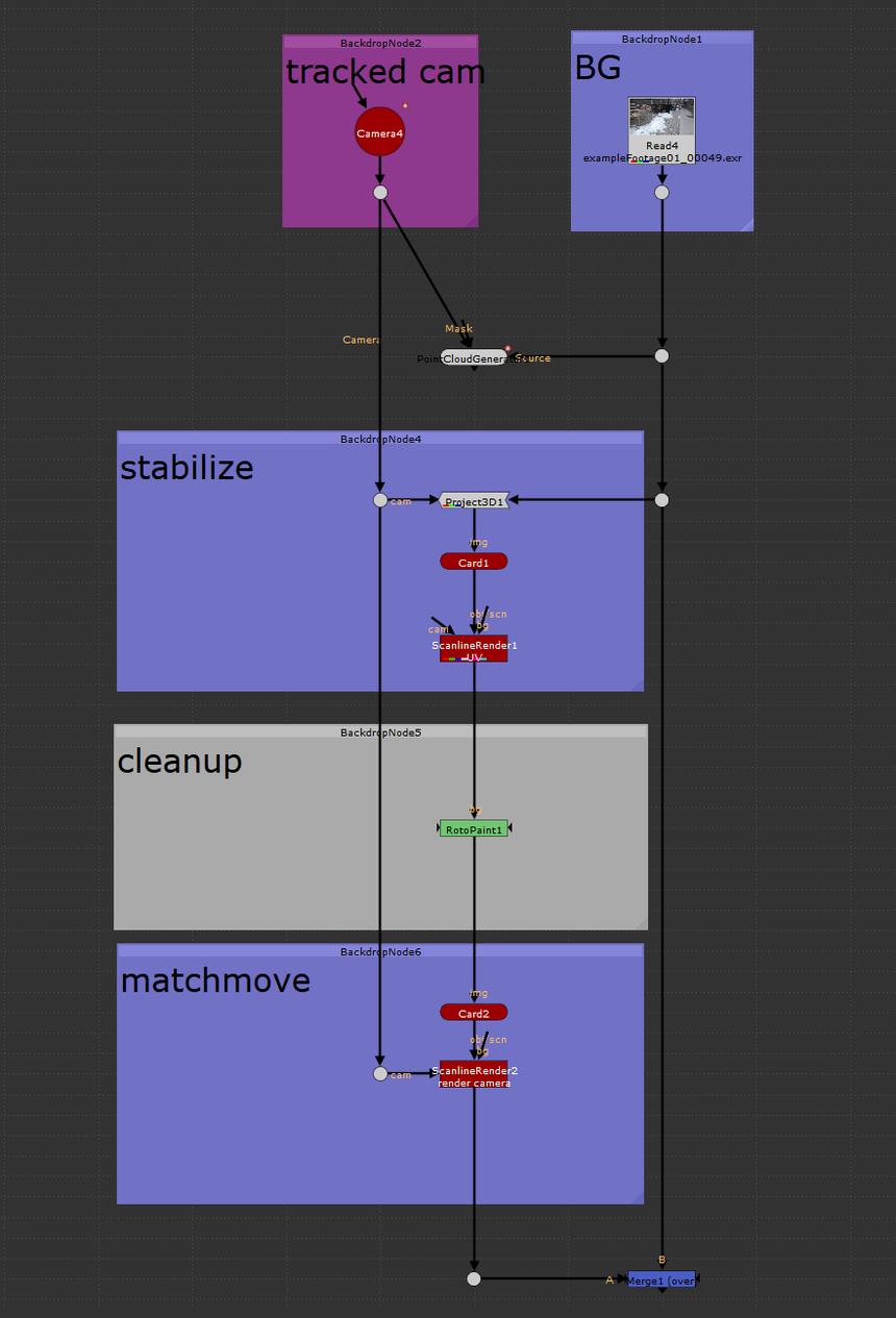  the problemWhen I first read about Han Cao's AutoFlare tool, I was itching to try it out on my next comp that needed a tasteful lens flare. I've used the H_AutoFlare countless times, it's intuitive and produces great looking lens flares quickly; leaving the need for building your own setup from scratch each time at the door. I often found myself only using a handful of the preset components at a time, I never needed the entire kit at once. The biggest headache I noticed when grabbing a few of the components was how long the AutoFlare node took to compute. It would quickly bog down my comp due to the large amount of Directional Blur nodes inside the AutoFlare group. I'd find myself setting the look inside the AutoFlare group, then picking out the pieces I needed before deleting the group entirely. This was a pain when I needed to go back and customize the look or feel of the flare. All the GUI sliders were gone and I had to search out which node was linked to what and how it was controlling the rest of the flare generator. the solution I took Han's sweet AutoFlare tool and added some simple disable boolean knobs for each of the components. This way, I'm able to tick which components I want enabled and have the components I don't want not be processed by Nuke when caching or at render time. Furthermore, I won't have to disassemble the group when I want to extract a small portion of the flare generator. The Directional Blur node is great at adding flavor to many of these lens flare components but it bogs down Nuke very fast and should be disabled when possible. My small change speeds up the performance of the group greatly, especially when there's only 1 or 2 components enabled. The images below show the profiles of an example comp with the regular AutoFlare on the left and the disable option AutoFlare on the right. The nodes are color coded using Nuke's built in Python performance timer. The timer calculates how resource intensive each node is as its being processed. The colors start at green (not intensive) and work their way up to red (most intensive). White denotes no calculations are needed. Both of these node graphs output the same image. In this example, I created a flare without the "Mirror1", "Ghost1", "Circle1" components, and without using a texture. You can see that the regular AutoFlare on the left, still has to process every single component, even when their values are set to 0. With the added ability to disable the components you don't need, amount of resources needed to calculate the final image is significantly less. This keeps the node customizable without needless extra computations. You might see the extra green on the regular AutoFlare and think that those processes won't take much time to calculate. Every extra computation you force Nuke to do will add up in the end, especially as your comp gets more complex. Saving a Nuke a bit computation time here and there can mean less waiting for caching or rendering, less precomping when the script gets heavy, and perhaps most important, more time for drinks at the end of the day. Hope you learned something! - Isaac
downloads
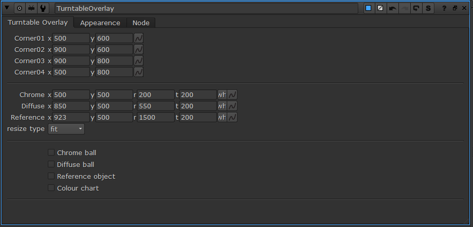
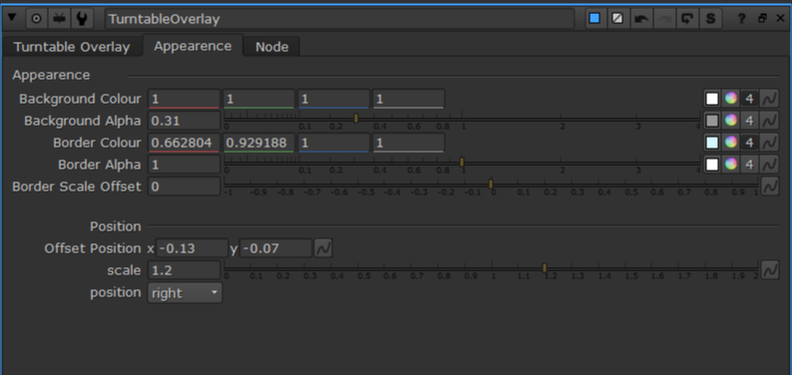
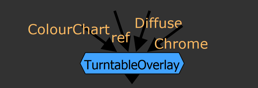 a long while ago... A long while ago, the CG supervisor at our studio asked for a hand in making a Nuke tool that would help him and his team better display the on-set references to the rendered references along with the CG render. He wanted a tool that could display the on-set chrome ball, matte ball, MacBeth chart, and reference objects in an adjustable way to fit any rendered shot. To meet these challenges, I created the TurntableOverlay node for Nuke. how do I use TurntableOverlay? To set up the overlay, begin by plugging in the pipes in the TurntableOverlay node to their respective images. Plug the Chrome and Diffuse pipe into an image that contains the chrome ball and diffuse ball, respectively. Plug the ColourChart into the MacBeth chart or similar colour reference guide. Finally, plug the ref pipe into any reference image. The pipes can be plugged into the same input, different input, or no input. Use the checkboxes at the bottom of the TurntableOverlay tab to select which inputs will be displayed in the overlay. The crop boxes for each input mark the rectangular section of the image will be displayed in the overlay. Use the appearance tab to adjust the background and border colours of the overlay, as well as the transparency. The offset position and scale knobs will move the overlay around the viewport while the position knob has a few predetermined positions to snap the overlay to.
how does it work?The guts of the group works by taking each piped in input and reformats the input image to the dimensions that the user specifies with the crop boxes. The reformatted image is merged with the background tile and border before being placed on a card. There are two sets of cards for each input, one for a vertical display, such as when the position knob is set to right or left, and the horizontal layout for when displayed horizontally. The cards are transformed and scaled uniformly to move anywhere in the viewport before exiting the group. This project is an ongoing learning process for myself and I’m sure there are many adjustments to be made to improve this tool. Feel free to reach out with any ideas on how to sharpen this concept and work out the kinks. I hope you find this tool useful in some capacity. Happy Programming! installation
Add this code to your menu.py which lives in the .nuke directory
 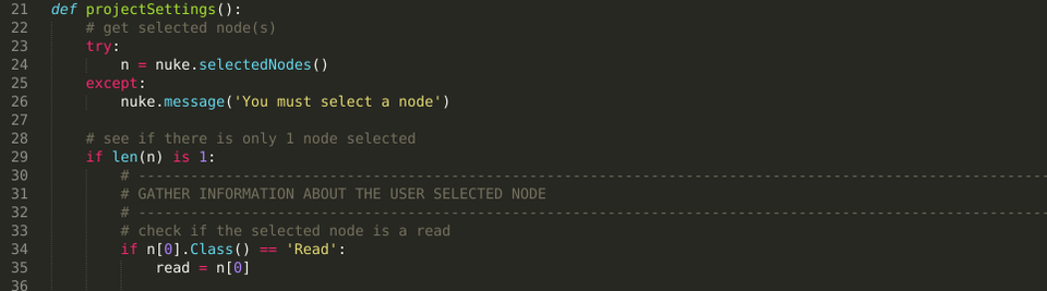 Download the script from Nukepedia here: www.nukepedia.com/python/misc/set-project-settings-from-read-node Description I've written a handy Python script that takes a look at the selected read node and sets the project full-size format, aspect ratio, and frame range to that of the read node. If the full-size format does not exist in the current user's list of formats, it prompts the user to name the new format and adds the new format to the dropdown menu before setting the project settings. Useful when first creating a script and you want to quickly set your project settings. I've used this script a handful of times when starting up a fresh Nuke project. The script makes setting project information snappy when you know that the read node you're bringing in is exactly right resolution, frame range, and aspect ratio as the output. The idea for this script came from some programming phrase that's something along the lines of "If you have to do a dull simple task more than twice, automate it." And that's exactly what this script aims to address. Setting the project settings has to be done every single time you start on a new shot and it requires multiple steps. Having the ability to adjust all the project information saves a few clicks and lets you get working faster. Happy programming! Installation
Part 1: The Label Left, my custom tracker. Right, Nuke default tracker The first step I take to organizing my Tracker node is to display the Reference Frame as well as the type of motion that the Tracker is currently using. Being able to view the Reference Frame without having to dive into the node is quick and can help when creating roto-shapes that will be attached to this Tracker. Seeing the output type is helpful for a similar reason, with a glance I can tell what type of motion I should be seeing when viewing the Tracker. This can be achieved with some simple Python code added to your menu.py file. Code Editor
Furthermore, I find it helpful to have the Tracker's reference frame automatically set to the frame when the Tracker was created. When I'm looking for an element to track, I place my Tracker node on the frame where I want to start my track. This line of code allows me to skip the extra clicks of going inside the node and selecting 'set to current frame'. Finally, there are a few more defaults that I adjust for my Tracker node. These are mostly personal preferences and are pretty straight forward so I'll refrain from writing more than what's necessary for them. I set my shutter offset to centered because cameras in the real world always have motion blur that's centered around an object. It's strange that nuke even has this as a default for so many nodes. However, I rarely use the Tracker for calculating transforms because it's quite slow compared to a baked Transform or Corner Pin (more on that later). I check 'adjust for luminance changes' which I find quite often gets me a better track. I also check 'hide progress bar', which is a total personal preference, I don't like seeing the bar pop up when I start tracking. I've seen some compers who like to put the progress bar in its own windowpane within Nuke's UI as well. I set the default export dropdown to 'Transform (match-move, baked)', more on that later on. In the end, the code in my menu.py looks like this Part 2: Baked Tracker/Corner Pin Naming 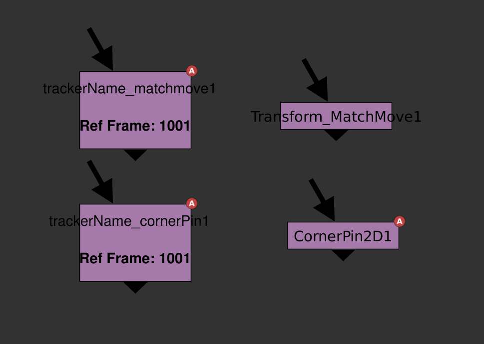 Left, my custom baked Transforms output from a Tracker named 'trackerName'. Right, Nuke's default output from the same Tracker. When tracking, I like to use the 'Transform (match-move, baked)' export option. I've found that linking Transform nodes to Trackers slows down my comps. The slow down may be caused by Nuke having to process both the Transform and the Tracker nodes when drawing up a frame. The big downside to this is that, by default, the baked Transform/CornerPin created from the Tracker is difficult to differentiate from regular old Transforms. Additionally, there's no easy way to tell which Tracker created that Transform. Being able to tell where a baked Transform came from is super helpful for other compers picking up shots and when I'm iterating through multiple Trackers. I've written a Python script that is called when the user presses the 'create' button with the Transform (match-move, baked) or CornerPin (match-move, baked) dropdown selected. I've left out the stabilize versions of these as I typically check the 'invert' checkbox within these nodes, to swap between matchmove and stabilize transformations. The script creates a Transform/CornerPin node and sets the nodes name with this format 'TrackerName_Matchmove' or 'TrackerName_CornerPin' depending on the drop down. It also adds in the Trackers reference frame to the label of the Transform. Here's a link to a GitHub page with the 'customTrackerIS.py' script. To use this script, you have to add these lines of code to your menu.py file: Part 3: Fast Toggle Tracker TRS Checkboxes
The final amend to Nuke's native Tracker node that I've implemented is a Python button, built into the node that allows me to quickly check or uncheck the translate, rotate and, scale options for all tracks within the Tracker. I do a lot of my tracking using Mocha and when I copy over a Tracker node from Mocha into Nuke, all the tracks inside the node are toggled off by default. I'd find myself having to click through every translate, rotate and, scale checkbox toggling them all on. Using the 'manage user knobs' in the Tracker node, I added three boolean knobs, one for each translate, rotate and, scale and a PyScript button. When pressed, the PyScript button will look at the three checkboxes, and change all tracks in the node to match the selected boxes. So if the user ticks off just the translate and presses the button, only the T (translate) knobs for all trackers will be checked. Here's a GitHub link to the TRS custom tracker node. Additionally, I've added a separate python script that allows me to quickly tick a specific column using a hotkey. To check all the boxes I can press shift+t, shift+r, and shift+e for translate, rotate, and scale, respectively (shift+s is bound by default for nuke's settings menu) Here's a GitHub link to the script. This script also needs some code added to the menu.py: That about wraps it up! I'm always looking for more ways to streamline my compositing process, if there's a better way I could be running things, shoot me a chat.
|
|||||||||||||||||||||||||||||||||||||||||||||||||||||