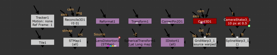
 the basics.An understanding of how Nuke handles 2D image transformations is essential for all Nuke artists, even if that understanding just scratches the surface level. Filtering methods and concatenation play an enormous role in maintaining the quality of the plate. The importance of reducing the degradation of the plate while working can not be stressed enough. There are a handful of great write ups on filtering for Nuke out there but since this topic is so important for all artists, I want to make that information more accessible for every compositor out there. filtering muddles your comps.A “filter hit” happens when Nuke resamples an image to remap each pixel coordinate to an integer value. Taking a filter hit will slightly degrade the image and will often be unavoidable at one point or another. Taking a few filter hits on different areas of the frame will most likely be okay, but the problems quickly emerge when multiple filter hits are needlessly created. In order to transform an image, Nuke will take the input coordinate of a pixel, apply the spatial transformation specified by the user, and then output the destination value for every pixel in the image. Filtering is necessary to help prevent jagged edges from appearing by applying an anti-aliasing filter across the image after it transforms. So what happens when the user places a transform node down and applies a translation of 0.5px in the x direction? A computer monitor is comprised of a coordinate grid of pixels where every pixel has an x and y value and every pixel is assigned a color. The values of each coordinate must be an integer because a pixel can only display a single color at a time. Transforming an image by half a pixel would prevent the image from being displayed on the monitor unless a filtering method is used to calculate integer values for all pixels before displaying. In essence, this is what’s happening when the user is applying transformations in Nuke. The user will apply a transformation which will create a whole bunch of non-integer pixels and Nuke will round those values into integers based on the filtering method that’s selected. A simple filtering method uses the original pixel values, while more complex algorithms apply sharpening and smoothing to make a more natural looking image. Choosing which filter to use can have a large impact on the quality of the output. The image below shows how Nuke handles an image transformation of 0.5px. Both images have a single white pixel in the center of the workspace. Image A uses a transform node with no translation, while image B shows the 0.5px translation. As you can see, the filter interpolated the 0.5px translation as two pixels each half the value as the original. Imagine doing this pixel "halving" across an entire image 2 or 3 or 4 times over, the overall image quality will surely degrade. 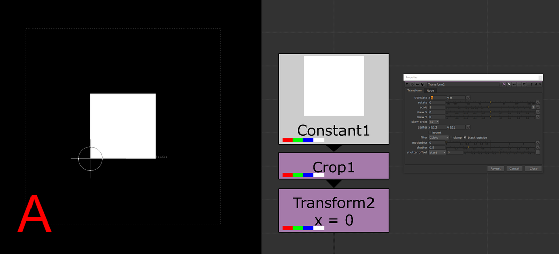 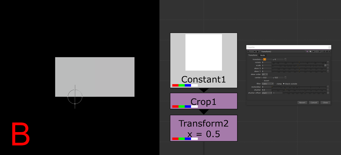 filter or motion blur or both.The quick rule of thumb to follow is that nodes with filter, motion blur, or both of those knobs will have some sort of filtering when used. Some examples include, but are not limited to, transform, card3D, spline warp, lens distortion, tracker, scanline render, and corner pin. Keep in mind that if the motion blur option is being used in any of these nodes, there will be two filter hits because motion blur is a filtering method on its own (Nuke processes spacial filters first then temporal). Furthermore, if you stack multiple transforms one after another, only the filtering method of the bottom-most transform in the stack will be applied, all others will be ignored. (see the “concatenation” section below for more details) choosing the right filtering method.The large amount of filtering methods available make choosing the right one for you a daunting task. I’ve divided the methods into different categories to help you choose the right method for your needs. At the top of the list are the methods that add the most sharpening to the image. As you move down the list, the methods become more smoothing intensive with the most smoothing at the bottom. I'd recommend experimenting with the different options to learn the unique properties each one has.
Heavy Smoothing Other
Additional information and further examples on the different filtering methods can be found on Ben McEwan's filtering blog or on Foundry's webpage on filtering. concatenation.All of the above information is great surface level knowledge on dealing with filtering in Nuke. Understanding how concatenation works in Nuke is the deep level knowledge that will sharpen your artist’s eye to better pick out minute details in your comps. Concatenation is one of the most important pieces of 2D compositing knowledge that any artist can start applying immediately. Above, I mentioned how you want to minimize the amount of filter hits that are needed to produce the final output, an understanding of concatenation is an understanding of how to minimize the damage on your plates from filtering degradation. Concatenation is Nuke’s ability to combine adjacent transformation operations into a single operation, which will be filtered a single time. Ben McEwan’s blog on filtering (link above) provides a great example. Rather than taking multiple operations with stops in between: 5+10 = 15, 15+2 = 17, 17+8 = 25; Nuke will do all those operations at once: 5+10+2+8=25 but only if the nodes performing the operations are of similar type (have a filter knob). Each of these operations is a link in the “concatenation chain” and at the end of the chain, Nuke will filter the values and display the image. Concatenating nodes of similar type will continue to add links in the chain until a non-concatenating node is added, at which point the chain will have break and a filter hit applied. When it comes to filter hits, you want to be minimizing the amount of broken links in your comp. 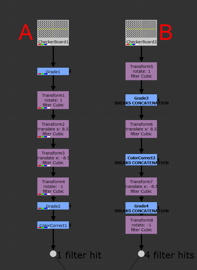 With the Transform node, you’ll want to be adjacently stacking the transform nodes in order to keep the chain links connected. Nuke will look at this stack and treat it as if it was a single transform operation and apply one filter method at the end of the stack. Since Nuke is treating the stack as a single operation, the rule is that only the filter at the end of the stack will be used, all filters above will be ignored. The image above shows two setups of identical nodes arranged in differing orders. Stack “A” minimizes filter hits from concatenation by arranging the transform nodes one after another in a linked chain; there aren’t any nodes between the transforms. This outputs an image with only one filter hit. Contrast that to stack “B” which has nodes breaking the transform chain. This output takes four filter hits while computing and the resulting image looks noticeably worse off. Take a look at the two outputs below, notice the fuzziness of output “B”. Four filter hits can make a huge difference! 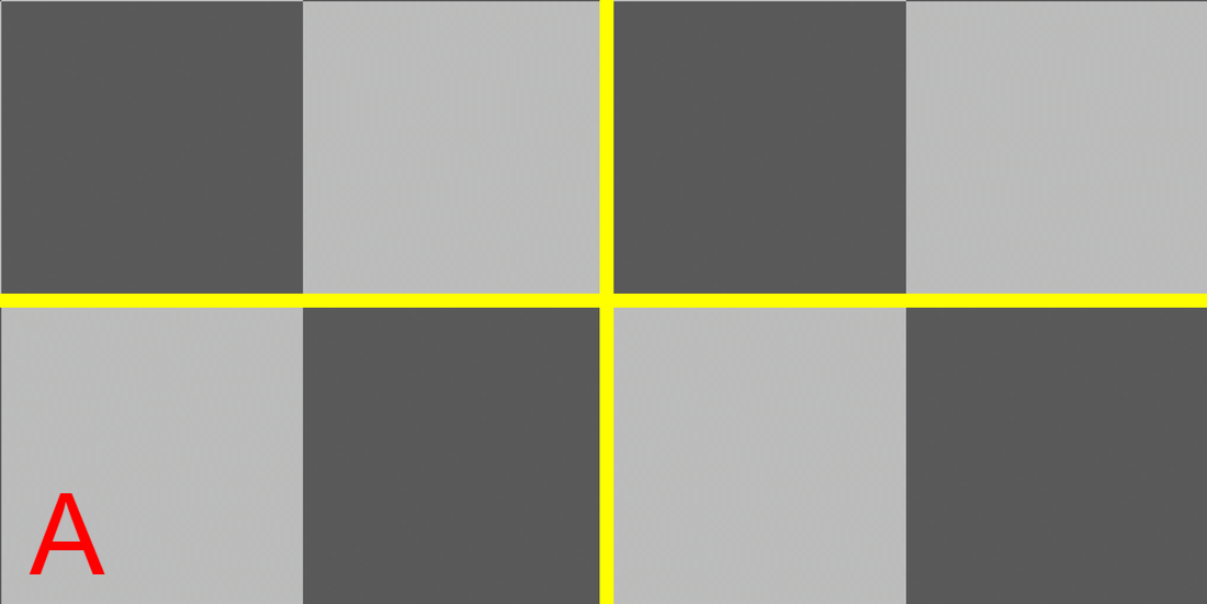 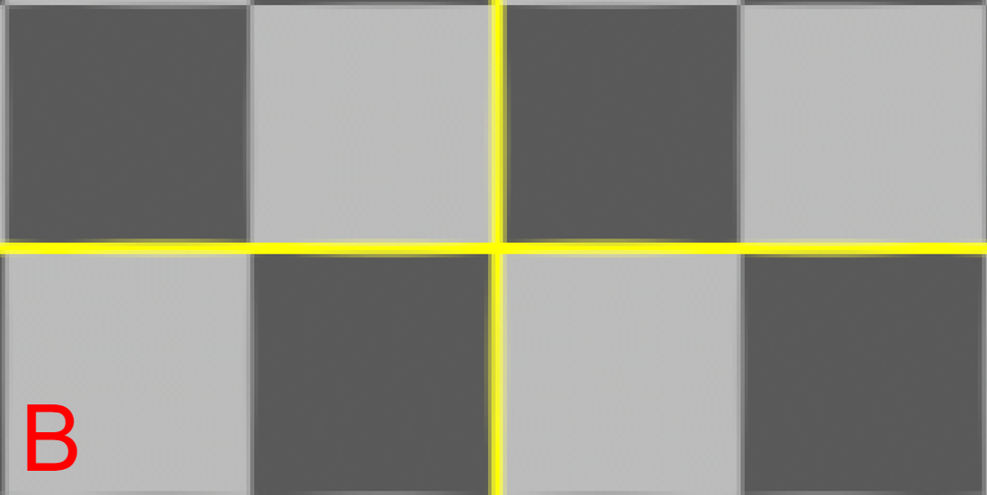 upstream and downstream.Not all filtering nodes play nicely with others. A handful of transformation nodes will end the concatenation as soon as they’re placed, without exception. Nodes that are upstream compatible will concatenate with nodes placed above, but will always cause a break in the chain below. The “motion blur” knob is an example of upstream compatibility. The motion blur knob in a transform is its own filter and when enabled, will add a filter hit alongside the spatial filter. If a transform node has the motion blur option enabled, it will always break the chain when it’s calculated. Other nodes are upstream and downstream compatible meaning they will play nicely with other transforms above and below without breaking the chain. Below is a comprehensive list of all concatenating nodes and their respective behaviors. Any node that is not on this list will cause a break in the concatenation chain. The quick rule of thumb to determine compatibility is that if the node has a filter and a motion blur knob, it will be upstream and downstream compatible. If the node has only a filter knob, it will only be upstream compatible. If a node has neither of these knobs, it will not concatenate (unless it’s a NoOp, dot, or switch). The only exception to this rule is for the reformat, which will concatenate upstream and downstream. 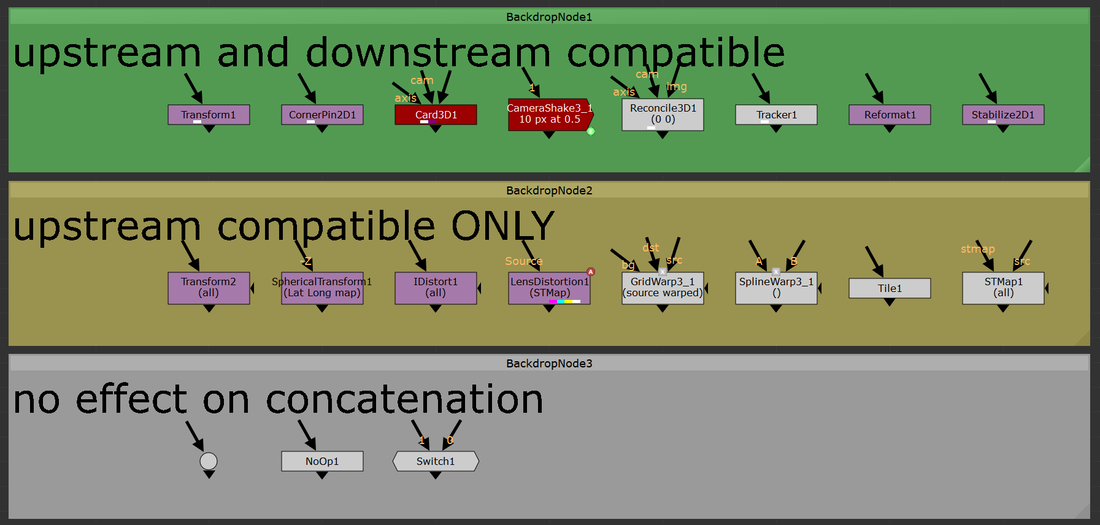 a note on 3D.At the very bottom of the concatenation knowledge ocean is knowing how 3D nodes will concatenate. Nuke is quite smart and will continue linking the chain of concatenation through the 3D system as long as no other breaks stop it. 2D transforms can be passed through the 3D system and to the ScanlineRender while still maintaining their concatenation. “Regular” Nuke geo (card, cube, cylinder, etc.) will not break concatenation. However, any imported geo will cause a filter hit. Furthermore, Project3D will not cause any damage which is quite powerful. I constantly find myself using Project3D in my cleanup work and knowing how to keep my images looking sharp even while getting passed through 3D is a huge improvement. a note on anamorphic footage. When working with non-square pixel aspect ratios in the past, I had become accustomed to using the Reformat node to dequeeze anamorphic plates, causing a filter hit right at the start of the comp. This filter hit can be removed entirely by setting the project settings to the desqeezed aspect ratio while also having the “ignore pixel aspect” checkbox disabled in the viewer node (the hotkey for this is ctrl+shift+p with the mouse hovering over the viewer). Nuke is typically good at maintaining image integrity when desqeezing using a reformat so the overall degradation of the plate is minimal here. Filter hits can add up fast and removing a filter hit entirely is an always welcome addition. minimizing the damage.More often than not, when using a high-sharpening filter, some sort of artifacting will become apparent. Look into areas of high contrast or super hot white values and you might notice a ringing that is typical of many sharpening algorithms. One way to combat this is to move to a log colorspace before applying the sharpening. I use the ColorSpace node set to “AlexaV3LogC” before I apply a heavy sharpening method to reduce the visual artifacting that may occur. Keep in mind the rules of concatenation here and be careful not to break the chain. High sharpening algorithms have the tendency to create negative values in their outputs, which can lead to a whole sort of issues down the line. It might be worth placing a clamp node to clamp the blacks to 0 in order to remove any negative pixels that have popped up. Remember to disable clamping for the whites. in closing.Phew! That’s all I’ve got for this subject. Filtering and concatenation is a dense topic that has major implications on the quality of plates in your comps. I constantly find myself learning new tidbits here and there on the intricacies of concatenation and the nodes that play into it. I hope you learned something new from this write up. Happy comping!
1 Comment
the how toIn this tutorial I cover how to setup and use the UV projection mode in the ScanlineRender node to make cleanup a breeze in Nuke. In my experience, I've found myself using this method to paint out dolly tracks or other objects on a flat surface. It's also came in handy when doing cleanup on pattern surfaces where painting from the camera's perspective might be challenging. The only thing you need to get this method working is a tracked camera for your shot. The better the camera track, the easier this type of cleanup will be. To get started, you'll need to place a card in 3D space over the area which you want to do your cleanup on. Think of this card as your cleanup canvas, anything that falls inside this card's area you'll be able to work on, anything that falls outside the card's area will not be able to be used. This method can be repeated using multiple cards if necessary. I used a PointCloudGenerator node to help me confirm that my card was where I wanted it in 3D space. Next, take a Project3D node and hook the inputs in to the tracked camera and the BG plate. Take your card and plug that into the Project3D. Next, drop in a ScanlineRender and hook that into the card. Set the "projection mode" knob on the ScanlineRender to "UV". This will have the ScanlineRender output the UVs of whatever geometry is plugged in, which is where we're going to be doing the cleanup. This ScanlineRender does not require a camera to be plugged in because UV maps can exist independently of the camera. Think of it like modeling geometry when in a 3D package. You can model the geo with UVs without needing a camera in your scene. With the viewer hooked up to the ScanlineRender set to UV, start working through the cleanup. After you've finished the cleanup, it's time to reverse the UV stabilize that we had set up above. Copy the card that was created earlier and hook it up at the bottom of your cleanup. Next, place a ScanlineRender node and connect the camera input to the tracked cam, and the obj/scn input to the copied card. This ScanlineRender needs to have its "projection mode" knob set to the default "render cam". Finally, merge your completed cleanup over the BG plate. All done! The image below shows the basic setup for using this stabilization technique. Thanks for reading and happy comping! 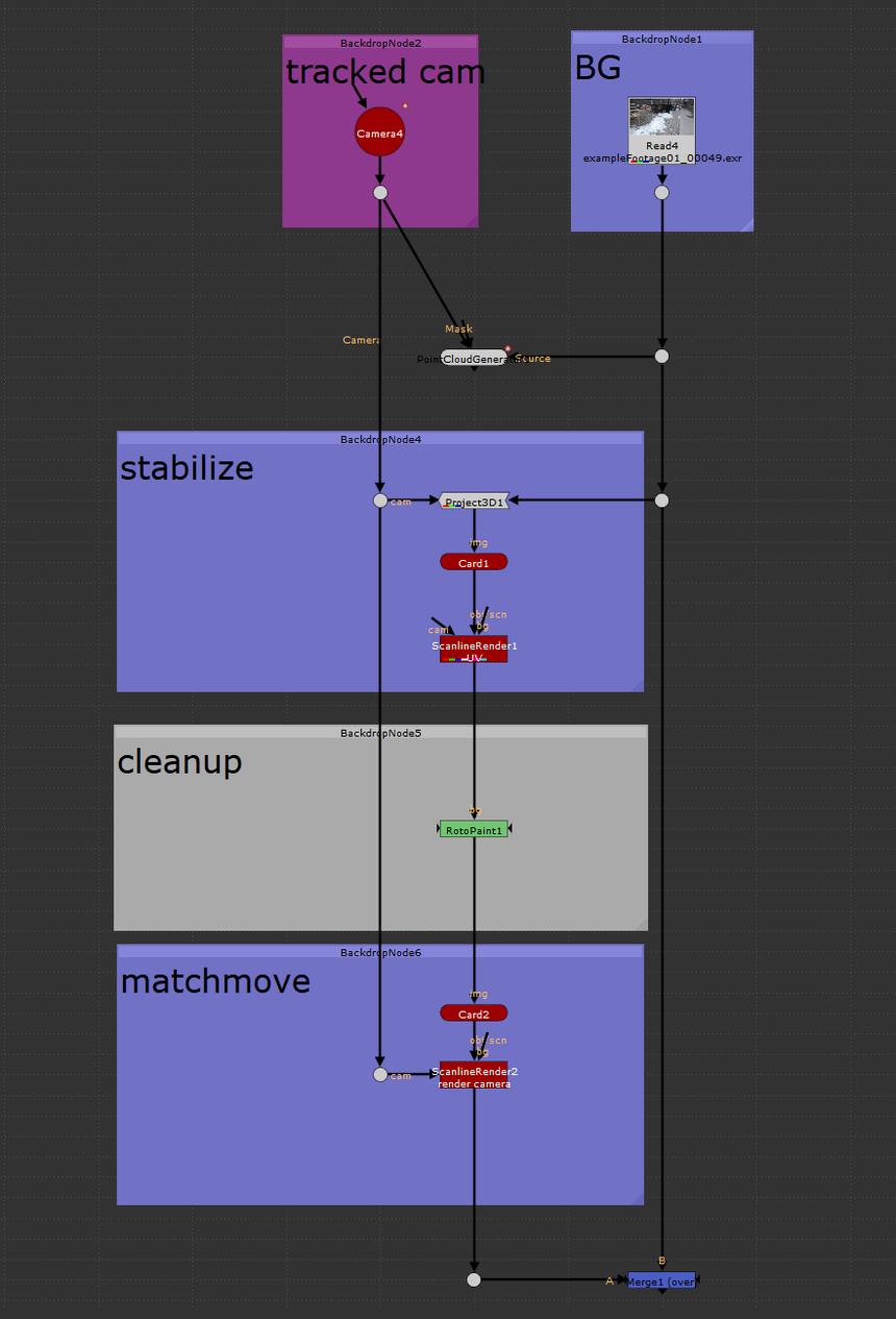 |